INFLUENCE LINE METHOD OF ANALYSIS
An influence line for any given point or section of structure is a curve whose ordinates represent to scale the variation of a function such as shear force, bending moment, deflection etc at a point or section, as the unit load moves across the structure.
Influence line for determinate structures:
(1) Simply supported beam:

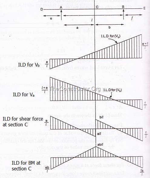
I.L.D. for reactions at the supports:
Let a unit load waves from the left end A to the right end B of the beam.

As’ x’ increases,  increases and
  decreases.
At x=0, ![clip_image004[1] clip_image004[1]](https://theconstructor.org/wp-content/uploads/2010/10/clip_image0041.gif) =0,
=0, ![clip_image005[1] clip_image005[1]](https://theconstructor.org/wp-content/uploads/2010/10/clip_image0051.gif) =1
=1
At x=l, ![clip_image004[2] clip_image004[2]](https://theconstructor.org/wp-content/uploads/2010/10/clip_image0042.gif) = 1,
= 1, ![clip_image005[2] clip_image005[2]](https://theconstructor.org/wp-content/uploads/2010/10/clip_image0052.gif) = 0
= 0
Thus, I.L.D. is shown in the figure below.
Uses of an Influence Line Diagram:
- To determine the value of the quantity for a given system of loads on the span of the structure.
- To determine the position of live load for the quantity to have the maximum value and hence to compute the maximum value of the quantity.

INFLUENCE LINE DIAGRAMS:
(1) For shear force at a given section of a simply supported girder

Let a unit load move along the span of a simply supported girder AB of span l.
Let D be a given section.
When the unit load is between A and D,
When the unit load is between D and B
(2) For the bending moment at a given section
When the unit load is between A and D.
When  ,
, 
When  ,
, 
When the unit load is between D and B,
When ![clip_image014[1] clip_image014[1]](https://theconstructor.org/wp-content/uploads/2010/10/clip_image0141.gif) ,
,
When  ,
, ![clip_image013[1] clip_image013[1]](https://theconstructor.org/wp-content/uploads/2010/10/clip_image0131.gif)

(3) Simply supported beam with overhanging

MULLER BRESLAU PRINCIPLE:
This principle states that if a reaction (or internal force) acts through an imposed displacement, the corresponding displaced shape of the structure is to some scale the influence line for force quantities only.
(4) Continuous Beams
Consider a continuous beam ABC shown in figure below. Let it be required to obtain the influence line for the vertical reaction ![clip_image005[3] clip_image005[3]](https://theconstructor.org/wp-content/uploads/2010/10/clip_image0053.gif) at A. Assume that the support A is removed (as in fig b). Let the given beam carry unit load at a. Let the corresponding reaction at A be
at A. Assume that the support A is removed (as in fig b). Let the given beam carry unit load at a. Let the corresponding reaction at A be ![clip_image005[4] clip_image005[4]](https://theconstructor.org/wp-content/uploads/2010/10/clip_image0054.gif) . Thus after removing the support at A, apply an external forces
. Thus after removing the support at A, apply an external forces ![clip_image005[5] clip_image005[5]](https://theconstructor.org/wp-content/uploads/2010/10/clip_image0055.gif) at A so as to maintain the beam in its position.
at A so as to maintain the beam in its position.

Now from Belti’s theorem,

This means that the ordinate of the influence line for ![clip_image005[6] clip_image005[6]](https://theconstructor.org/wp-content/uploads/2010/10/clip_image0056.gif) at the point n is obtained by dividing the deflection at n by the deflection at point a.
at the point n is obtained by dividing the deflection at n by the deflection at point a.
Thus, influence line diagram for ![clip_image005[7] clip_image005[7]](https://theconstructor.org/wp-content/uploads/2010/10/clip_image0057.gif) is given by
is given by

(5) Propped Cantilever
Figure (a) below shows a propped cantilever AB fixed at A and simply supported at B.
Let ![clip_image005[8] clip_image005[8]](https://theconstructor.org/wp-content/uploads/2010/10/clip_image0058.gif) and
and ![clip_image004[3] clip_image004[3]](https://theconstructor.org/wp-content/uploads/2010/10/clip_image0043.gif) be the reacting forces at A and B respectively.
be the reacting forces at A and B respectively.
To draw the influence line for ![clip_image004[4] clip_image004[4]](https://theconstructor.org/wp-content/uploads/2010/10/clip_image0044.gif)
Remove the support B and apply unit load at any point distance ‘x’ from left support (fig b). Again apply a unit load at right end and displacements were measured at those two points.
As deflection at B is zero, therefore,

As per Belti’s Law;
Thus, we can write

Thus the ordinate of the influence line for ![clip_image004[5] clip_image004[5]](https://theconstructor.org/wp-content/uploads/2010/10/clip_image0045.gif) is obtained by dividing the deflection at any section X by the deflection at the point B due to unit load B.
is obtained by dividing the deflection at any section X by the deflection at the point B due to unit load B.


Comments
Post a Comment